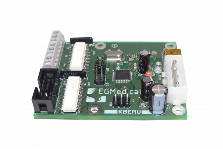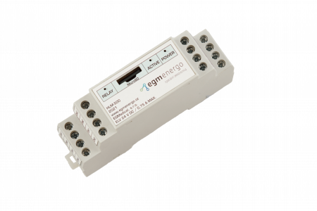
The EZ a is a simple electronic load designed for installation in a switchboard. The device loads the connected source with a constant DC current, the magnitude of which is controlled by the voltage input of the device.
For its function, the instrument needs an external power supply for the electronic part; this power supply branch is galvanically connected to the load circuit by its negative pole.
The output relay of the device indicates the correct operation of the device: the thermal protection is not active, the desired current through the load circuit is reached and the voltage on the load circuit (i.e. the voltage of the connected power supply) is higher than the user-set limit, see section “The voltage of the load circuit is higher than the user-set limit”. 5.
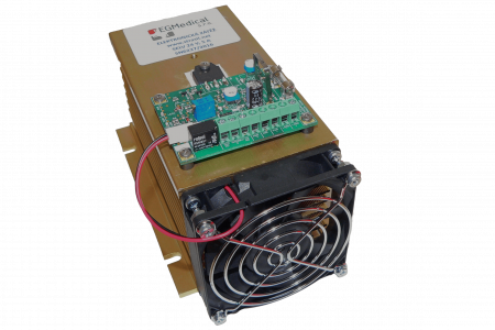
When installing, make sure the cooling is of good quality – the power loss of the device, including the electronics, can be up to 200 W.
Be careful not to exceed the maximum power dissipation of 125 W (5 A @ 25 V) in continuous operation or 187.5 W (7.5 A @ 25 V) in max mode by adjusting the current and voltage settings. 5 minutes on, 5 minutes off.
Use four M5 screws for mounting.
The device is connected to the circuit by means of screw terminals, which are designed for salted conductors with a cross section of 0.25 – 1.5 mm2 with a hollow core or for conductors 0.5 – 2.5 mm2with a solid core.
Connecting devices
The meaning of the terminals is as follows:
| Mark | Functions |
|---|---|
| RL | Input signal for RL function (> 20 V on; < 2 V off) |
| OUTPUT | (pairs of clamps) Switching contact of the output relay. |
| PWR + | Positive pole of the power supply of the electronic part (20 – 28 V = / 0.3 A, max. 4 A/F). When this supply voltage is lost, the load circuit is disconnected and the output relay is removed. |
| INP | Control voltage 0 – 10 V. The device conversion is 7.5 A / 5 V, i.e. for a voltage of 5 V the load current is 7.5 A. Do not use control voltages higher than 5 V without consulting the manufacturer – you will exceed the permitted operating parameters of the device. Do not exceed 10 V (max. 11 V) at this terminal! The negative pole of the control voltage is at the PWR – terminal. |
| PWR – | Negative pole of the power supply of the electronic part. |
| LOAD – | Negative pole of the load circuit. Plug in the loaded power supply here. This terminal is internally connected to the PWR – terminal; however, do not interchange the terminals for best possible accuracy. |
| LOAD + | The positive pole of the load circuit. Plug in the loaded power supply here. Caution: the LOAD+/LOAD- terminals must not be re-polarized. |
RL functions
By supplying a signal to the RL terminal, a special mode of operation of the device is switched on, when a load resistor of 3 Ω +- 10% is connected to the LOAD-/LOAD+ terminals. In this mode, the RL LED is lit; the OK LED is lit if the output voltage of the loaded power supply does not drop.
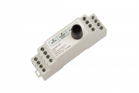
Instrument settings
The device is equipped with three elements for calibration and adjustment:
| Mark | Functions |
|---|---|
| Gain | UNMANIPULATE USERS: completing the steepness of the INP input transfer |
| Offset | NON-EMERGENCY: offset (current at zero voltage at INP input) |
| UV-SE(tup) | Setting the voltage at the LOAD+ terminal at which the output relay switches. Default setting 20 V +- 10%. |
Signalling elements
There are three signal LEDs on the PCB:
| Mark | Functions |
|---|---|
| PWR | Presence of supply voltage of the electronic part |
| TEMP | Thermal protection active – load off |
| RL | RL function active |
| OK | Output relay closed (i.e., voltage in load circuit, no thermal protection active, no internal fault) |