STELM: DC electricity meter - DC electricity meters

Meter for DC systems:

  • Photovoltaic island systems
  • Accumulator systems
  • Fuel cells
  • Electric traction
More information
STELM: DC electricity meter – DC electricity meters

Description

We offer custom manufacturing of electric meters for DC systems in the accuracy class corresponding to TP 0.5 S of AC electric meters.

Electricity meters are suitable for use in the following fields:

  • measurement of production of solar systems (PV systems), especially in island systems (calibration of CMI Brno),
  • measurements in battery devices (especially in the bidirectional variant),
  • measurements in electric traction circuits (in bidirectional version also for equipment with regeneration),
  • measuring the power and consumption of other DC systems (e.g. fuel cells, 48 V telecommunication systems, etc.).

The device is manufactured in a DIN rail version in a sealable housing with a width of 5 modules. On the front panel of the device there is an electromechanical counter and a status LED. The standard accuracy of the instrument corresponds to TP 0.5.

The instruments are not type-tested, so they are not intended for billing measurements without prior consultation.

Download

What to order

Meter design

When designing equipment with a meter, it is necessary to consider the requirements for voltage and current ranges, the power supply to the equipment and the accuracy required.

The type designation of the instrument is according to the selected ranges and variants of the STELM 12-UIKX version, where the alphanumeric data U, I, K and X are selected according to the following tables.

Voltage ranges

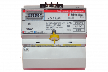
The required voltage range is determined by the range of voltages occurring in the measured network. Especially for photovoltaic applications, the maximum system voltage without load must also be considered.

In some applications, the instrument is powered from the measured voltage in the same way as is customary for AC instruments. In addition to the advantage of saving a separate power supply, this solution has a significant disadvantage for some applications: there is a lower voltage limit in the system, determined by the characteristics of the meter’s power supply, and if the voltage drops below this limit, the measurement does not run. This problem is encountered, for example, when measuring the consumption of photovoltaic-powered heaters, when the voltage in the system drops under low light conditions, e.g. to 40 V from the nominal 300 V, but the panels still transmit measurable power and it is a shame not to read it with the meter. In this case, we then use instruments with a separate power supply, capable of measuring from zero input voltage.

The design of the instrument with a separate power supply has two variants: with direct voltage measurement, where the measured voltages are fed directly to the terminals of the instrument, and a variant with indirect voltage measurement, where an external isolation voltage converter is used for voltage measurement. The measuring range is then determined by the input range of this isolation transducer; we can supply an isolation transducer or any commercially available type can be used.

The connected (separate) power supply is of course galvanically isolated from the measuring and communication terminals of the instrument.

Voltage type code
(letter U in type
devices)
Voltage measurement rangeInstrument power supply
A9 – 36 Vfrom the measured voltage
T18 – 75 Vfrom the measured voltage
V40 – 100 V (25 – 100 V by agreement)from the measured voltage
F60 – 150 Vfrom the measured voltage
S125 – 360 Vfrom the measured voltage
00 – 750 V directlyseparate power supply (9 – 36 V)
10 – 750 V directlyseparate power supply (18 – 75 V)
20 – 50 kV (indirect 0 – 5 V)separate power supply (18 – 75 V)
30 – 50 kV (indirect 0 – 10 V)separate power supply (18 – 75 V)
Current ranges

The meters are designed for external shunt connection. As standard, we supply German Weigel TP 0.5 shunts with a marking to the default shunt resistance accuracy corresponding to TP 0.2 – these shunts are included in the price of the instrument. The voltage drop across the shunt at full current load is 0.1 V, so at a current of 100 A there is a 10 W loss across the shunt.

Between the device and the shunt we insert protective DC fuses, which are also included in the delivery of the device.

For special cases, it is to supply an instrument for indirect current measurement through an external isolation transducer, which is mainly used in high-voltage applications. Another case where this type of instrument is used is measurement with non-contact DC transducers, which allow lossless current measurement (no heat loss at the shunt) at a significantly higher cost and lower accuracy.

Current type code
(letter I in
type of device)
Current measurement rangeMeasurement type
00 – 15 Astraight (sidewall included)
10 – 25 Astraight (sidewall included)
20 – 60 Astraight (sidewall included)
30 – 150 Astraight (sidewall included)
40 – 250 Astraight (sidewall included)
50 – 400 Astraight (sidewall included)
*higher ranges by agreementstraight (sidewall included)
P0 – 50 kA (indirect 0 – 5 V)Indirect
D0 – 50 kA (indirect 0 – 10 V)Indirect
Communication

The instrument is equipped with only a pulse (S0) output in the basic version. It is a galvanically isolated open-collector type output that emits a number of pulses corresponding to the measured energy; the conversion constant is indicated on the instrument label and is e.g. 1000 imp/kWh.

For more advanced systems, we offer a version of the instrument with a MODBUS-RTU communication module or with an RS-485/ASCII communication module.

Both communication modules allow the transmission of voltage, current, power and energy readings from the start of the meter power supply. Both types of communication modules use the RS-485 bus and are galvanically isolated. The MODBUS-RTU communication module works with the standard MODBUS-RTU bus, to which up to 32 meters can be connected; the RS-485/ASCII communication module is designed for systems with a single meter – this module transmits data in the form of a comma or a line. semicolon separated data fields, readable in a normal terminal. This data output is also used to coordinate with the load controller for photovoltaics.

Communication type code
abilities (letter K
in the device type)
Communication skills
0only pulse S0 output
1RS-485/ASCII + pulse S0 output
2MODBUS-RTU + pulse S0 output
Special design

The letter X in the type designation of the STELM-UIKX is replaced by a list of special modifications according to the following table:

Type code of special
design (letter X
in the device type)
Meaning of
Cinstrument calibration (CMI Brno)
Bdesign for operation in both polarities of current. This design is suitable for measurements on battery-powered equipment or on equipment with regenerative power (electric traction, trams).
Udesign for operation in both voltage polarities
Qdesign for operation in both polarities of voltage and current (for AC networks we use the term four-quadrant meter)
Nin accordance with the standards for AC devices, the measurement stops if the current drawn does not exceed 1/1000 of the rated current of the meter. The “N” version has this function disabled.
SCalibration to TP 2.5 instead of (standard) TP 0.5
Mshunt connected in the negative pole instead of the positive

Price list

And how much can you get it for?

Type code of the stream:012345P or D
Current measurement range0 – 10 A0 – 25 A0 – 60 A0 – 150 A0 – 250 A0 – 400 Aindirect measurement.
Voltage type code:Voltage measurement rangeNap. instrumentshigher current ranges please inquire 
A9 – 36 Vfrom the measured voltage8 300 CZK8 800 CZK9 300 CZK9 700 CZK12 300 CZK14 300 CZK7 000 CZK
T18 – 75 Vfrom the measured voltage8 200 CZK8 700 CZK9 200 CZK9 600 CZK12 200 CZK14 200 CZK6 900 CZK
V40 – 100 V
(by agreement 25 – 100 V)
from the measured voltage8 400 CZK8 900 CZK9 400 CZK9 800 CZK12 400 CZK14 400 CZK7 100 CZK
F60 – 150 Vfrom the measured voltage11 200 CZK11 700 CZK12 200 CZK12 600 CZK15 200 CZK17 200 CZK9 900 CZK
S125 – 360 Vfrom the measured voltage10 200 CZK10 700 CZK11 200 CZK11 600 CZK14 200 CZK16 200 CZK8 900 CZK
00 – 350 V direct (0 – 750 V direct: extra charge 2700 CZK)separate power supply (9 – 36 V)8 300 CZK8 800 CZK9 300 CZK9 700 CZK12 300 CZK14 300 CZK7 000 CZK
10 – 350 V direct (0 – 750 V direct: extra charge 2700 CZK)separate power supply (18 – 75 V)8 200 CZK8 700 CZK9 200 CZK9 600 CZK12 200 CZK14 200 CZK6 900 CZK
2,3Indirectseparate power supply (18 – 75 V)7 900 CZK8 400 CZK8 900 CZK9 300 CZK11 900 CZK13 900 CZK6 600 CZK

Availability and delivery time on request. Minimum order 3 pcs per type.

Surcharges

Communication type code: Type code for special designs:
0imp. output S00 KčCinstrument calibration (CMI Brno)3000 CZK
1S0 + RS-485/ASCII2100 CZKBdesign for operation in both polarities of current. This design is suitable for measurements on battery-powered devices or
on equipment with heat recovery (electric traction, trams).
2900 CZK
2S0 + MODBUS-RTU4000 CZKUdesign for operation in both voltage polarities1780 Kč
Qdesign for operation in both voltage and current polarities
(for AC networks we use the term four-quadrant meter)
4680 Kč
Nin accordance with AC standards, the measurement stops if the current draw does not reach
1/1000 of the rated current of the meter. The “N” version has this function disabled.
0 Kč
Slower accuracy (TP 2.5) instead of (standard) TP 0.5-800 CZK
Mthe shunt placed in the negative pole instead of the positive pole1200 CZK

Contact us

Interested in a quote for a DC meter?

Contact us for a quote!

    Check

    Another
    products

    All products

    Interested in custom electronics design?

    Do you need modern and reliable electronics? Outsource part of electronics design? Or you need a complete new product or system? Let us know! We are happy to help you with small and complex applications.

    Write to us